When you open a new Warn winch box, that folded diagram is your most important tool. The Warn winch wiring schematic is the official map from the manufacturer. It shows you exactly how everything connects: the motor, contactor, and power cables.
Think of it as your roadmap for a safe and functional installation. Following it ensures every component communicates correctly. This prevents electrical shorts and makes sure your winch works when you need it.
Deciphering Your Winch Wiring Diagram
Before touching a wire, take a minute to read the schematic. This diagram is a map of your winch’s entire electrical system. It lays out the relationship between the winch motor, contactor, and power cables.
Nailing this part is the foundation of a good install. If you need a refresher, our guide on how to wire a winch is a great start. Getting familiar with the layout helps you spot key components and connection points.
To help you get your bearings, here’s a quick rundown of the main parts you’ll see on a Warn schematic.
Key Components on a Warn Winch Schematic
| Component |
Function & Symbol |
Common Location |
| Winch Motor |
The powerhouse of the system, represented by a circle with an “M.” |
The main cylindrical body of the winch. |
| Contactor Pack |
A heavy-duty relay that switches power to the motor, shown as a box. |
Usually a sealed box mounted on or near the winch. |
| Battery |
The vehicle’s power source, symbolized by stacked parallel lines. |
Your vehicle’s 12-volt battery. |
| Winch Controller |
The handheld remote or switch you operate, depicted as a switch symbol. |
The plug-in remote that controls “in” and “out” functions. |
| Power Cables |
Heavy-gauge wires for high-current flow, shown as thick lines. |
The red (positive) and black (negative/ground) cables. |
Once you can identify these parts on paper, matching them to the physical components becomes much easier.
Key Circuit Configurations
Warn winches generally use either a 5-wire or 6-wire circuit setup. The type you have dictates how everything connects. This is often paired with a standard control pack or a more integrated design.
For example, a classic Warn M8 typically uses a 5-wire circuit with a traditional control pack. In contrast, a modern 9.5Ti often has a 6-wire circuit with an in-line configuration.
Figuring out your winch’s system is the first real step, so check the diagram closely.
Gathering Your Tools and Safety Gear
Before using your Warn winch wiring schematic, we need to discuss preparation. Getting this part right is crucial for doing the job safely.
First, kill the power by disconnecting the negative terminal on your vehicle’s battery. This simple step prevents a nasty electrical short.
With the truck safely inert, it’s time to lay out your tools. Get organized now, so you can focus on making clean, solid connections later.
Essential Toolkit
You don’t need a professional tool chest, but a few key items will make a huge difference. Having the right tools for the job is essential.
Here’s what you absolutely need:
- Socket and Wrench Set: For mounting the winch and tightening electrical terminals.
- Wire Strippers and Crimpers: Crucial for prepping cable ends and getting a solid crimp.
- Heavy-Duty Cable Cutters: Standard cutters won’t work on thick winch cables.
- Drill and Bits: For mounting the contactor pack or drilling a pass-through for wiring.
- Safety Glasses and Gloves: Always protect your eyes and hands when working with batteries and tools.
Getting these items ready will make the whole process much smoother.
Connecting the Winch Motor to the Contactor
Let’s get your Warn winch wiring schematic off the page and onto your rig. It’s time to connect the contactor pack to the winch motor. This is where the electrical muscle of your setup comes together.
Look at your winch motor and you’ll spot terminals, usually labeled A, F1, and F2. These correspond to the colored cables from your contactor. A clean, tight connection here is non-negotiable.
A loose terminal creates resistance and heat, which robs your winch of power.
Cable Routing and Connections
How you run these heavy-gauge cables is just as critical as the connections. You must keep them clear of hot engine parts and sharp metal edges. A few zip ties securing the cables will give you a clean, safer installation.
A common mistake is running the cables bare. Engine heat and vibrations can chew through insulation, creating a dangerous short circuit. Wrap them in a wire loom or conduit for protection.
Modern winch kits are improving this process. The collaboration between Ford Performance Parts and Warn on the Super Duty Winch Kit is a great example. It includes a harness designed to plug right into the truck’s electrical system.
This approach guarantees a solid +12V supply and a bulletproof ground. That is essential for consistent performance under a heavy pull.
Wiring the Main Power and Ground Cables
Now we connect the main power and ground cables. This is where your Warn winch wiring schematic becomes a reality. Your winch requires a direct connection from the contactor to your vehicle’s battery.
A solid ground is just as important as the positive cable. Run the main black ground cable from the contactor to a clean, unpainted spot on your vehicle’s frame. Use a wire brush to scuff the contact point to ensure a perfect metal-to-metal connection.
Securing Your Power Lines
Routing these heavy cables correctly is a big deal for long-term reliability. Protect them from chafing, heat, and getting snagged. This is the same principle as choosing the right winch line, which we cover in choosing between wire cable and synthetic rope for your winch.
A non-negotiable part of a safe installation is proper circuit protection. This usually comes as a fuse or a circuit breaker. If a dead short occurs, this device prevents a potential fire by cutting power.
Here’s a quick look at how fuses and circuit breakers compare.
Fuse vs. Circuit Breaker for Winch Protection
This table breaks down the two most common ways your winch’s electrical circuit is protected.
| Feature |
Fuse |
Circuit Breaker |
| Operation |
A one-time use device that melts to break the circuit. |
A resettable switch that trips to break the circuit. |
| Cost |
Very inexpensive to replace. |
Higher initial cost. |
| Convenience |
Requires carrying spares and tools for replacement. |
Can be reset with the push of a button or flip of a lever. |
| Best For |
Simple, cost-effective protection where overloads are rare. |
Systems where nuisance trips or frequent overloads might occur. |
Ultimately, both get the job done. Just make sure your system has one of them, rated correctly for your winch’s amperage draw.
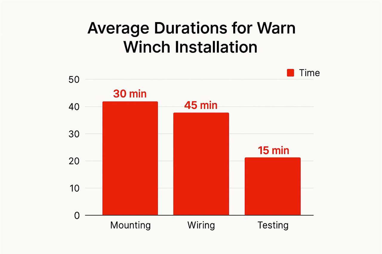
As the chart shows, wiring takes time. This is where patience pays off. A clean, secure, and protected wiring job is the key to a reliable winch.
Installing the Controller and Final System Checks

We’re on the home stretch. With the heavy cables run, it’s time to connect the controller. This is how you’ll tell your winch what to do.
The control socket usually plugs right into the contactor pack. This connection sends your “winch in” and “winch out” commands to the motor. Make sure this connection is solid and clean to avoid intermittent power.
Tidying Up the Wiring
This next part separates a quick install from a professional one. Use zip ties to secure all cables neatly along your vehicle’s frame. The goal is to keep them from snagging or rubbing against moving parts.
I’ve seen winches fail because a cable was left dangling. It either chafed through or melted on a hot exhaust manifold. Always slide a protective wire loom over your cables in high-risk areas.
The Final Once-Over Before Powering Up
Don’t reconnect that battery terminal yet. A final system check is critical. Grab your schematic and trace every connection one last time.
- Motor Terminals: Check that the A, F1, and F2 cables are on the right posts.
- Contactor Power: Are the main positive and negative cables wrench-tight?
- Vehicle Ground: Is your ground cable bolted to clean, bare metal?
- Controller Socket: Is the controller plug pushed in all the way?
Once you’ve confirmed everything matches your diagram, you can reconnect the battery. Knowing the fundamentals of how to use a winch safely will make this first test smoother.
Common Winch Wiring Questions
Even with a perfect Warn winch wiring schematic, questions can pop up. Every rig has its own quirks. Let’s run through some common snags.
One classic mix-up is swapping the F1 and F2 motor terminal wires. The good news is, it won’t fry anything. It will simply reverse your winch’s operation, so swap them back for safe use.
Extending Cables and Power Supply
A frequent question is about extending the main power cables. You can do it, but you must use wire of the same gauge or thicker.
Using a smaller wire is dangerous. It causes a major voltage drop, starves your winch of power, and creates a fire hazard. Always use quality connectors and seal splices with heat-shrink tubing.
This brings up why the winch wires directly to the battery. Under load, a winch pulls a massive amount of current—300-400 amps or more. Your vehicle’s standard wiring can’t handle that, making a direct connection essential.
A dual battery setup isn’t mandatory, but it’s a game-changer for serious off-roading. It isolates your starting battery, so you never have to worry about winching and then not being able to start the engine. It’s a smart upgrade for trail reliability.
For more expert guides and in-depth tutorials on off-road gear and vehicle preparation, explore the resources at Offroading.com. Visit us at https://www.offroading.com to get your rig ready for any adventure.
https://offroading.com/warn-winch-wiring-schematic/?utm_source=rss&utm_medium=rss&utm_campaign=warn-winch-wiring-schematic
Did you miss our previous article...
https://manstuffnews.com/4x4-off-road-cars/7-genius-truck-bed-storage-ideas-for-overlanders-in-2025