Trying to wire up a new Warn winch can feel intimidating. You have heavy-gauge wires, a complex control box, and expensive gear you don’t want to fry. Your Warn winch wiring diagram is your best friend in this process.
Think of it as a treasure map, not just a technical schematic. It shows you exactly how to get power from your battery to your winch motor safely. Getting this right is the most critical step to a successful installation.
Cracking the Code of Your Warn Winch Wiring Diagram
Understanding the diagram is key to a smooth install. It translates a confusing electrical circuit into a simple, followable plan. This visual guide will save you from a frustrating afternoon of troubleshooting.
The diagram shows where the power cables go and how the control pack integrates. It also details how the remote control talks to the winch. Following this map ensures the high electrical current is managed correctly.
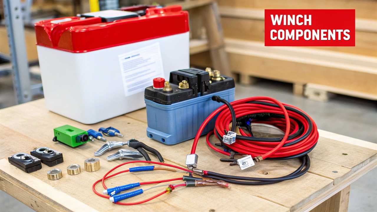
The Key Players on the Diagram
Your diagram features a few core components common to every Warn winch setup. Familiarize yourself with these, and the entire system will make more sense.
- Winch Motor Posts: These connection points on the motor are usually labeled A, F1, and F2. They receive power from the control pack to make the motor spin.
- Control Pack (Solenoid Box): This is the brain of the operation, housing heavy-duty switches called solenoids. These solenoids direct power to spool the cable in or out when you use the remote.
- Main Power Cables: These are the thick red (positive) and black (negative) wires. They are built to handle the high-amperage current needed to run the winch motor.
This system is the gold standard for a reason. WARN Industries holds a massive 20-25% of the global electric winch market. This means millions of off-roaders trust these diagrams for their installations. You can explore more data on the growing electric winch market to understand its importance.
Before routing cables, it helps to have a quick cheat sheet. Warn uses a standard color-coding system to simplify the process.
Warn Winch Cable Color and Function
| Cable Color |
Connects To |
Purpose |
| Red (Thick) |
Battery Positive (+) Terminal |
Main positive power supply for the entire winch system. |
| Black (Thick) |
Battery Negative (-) Terminal |
Main ground connection, completing the primary circuit. |
| Red (Thin) |
Control Pack & Solenoid |
Powers the control circuit from the ignition or battery. |
| Yellow |
Solenoid to Motor Post |
Directs power to one side of the motor field for spooling in. |
| Blue |
Solenoid to Motor Post |
Directs power to the other motor field post for spooling out. |
| Black (Shorter) |
Control Pack to Motor Post |
Grounds the control pack to the winch motor housing. |
Having this table handy can save you from constantly double-checking the diagram. Once you know these connections, you can start laying out your components.
Getting Your Tools and Safety Gear Together
A good install begins with laying out your gear before you start. You need a solid socket and wrench set. Quality wire strippers, a crimper, and a heat gun are also essential for a clean job.
Don’t overlook the small items, as they make a huge difference.
- Heat shrink tubing is your best friend for weatherproofing connections.
- A bag of zip ties is non-negotiable for neatly securing your wiring.
Safety First, Always
Before connecting a single wire, focus on safety. The first step is to disconnect your vehicle’s battery. Always remove the negative terminal first to prevent accidental shorts.
You are dealing with a system that pulls hundreds of amps. Protective gloves and safety glasses are essential. They protect you from potential sparks or battery acid.
This is about doing the job right. Following the official Warn winch wiring diagram is critical for safety and reliability. Improper installation is a major compliance issue, as detailed in reports on the importance of winches in regulated markets.
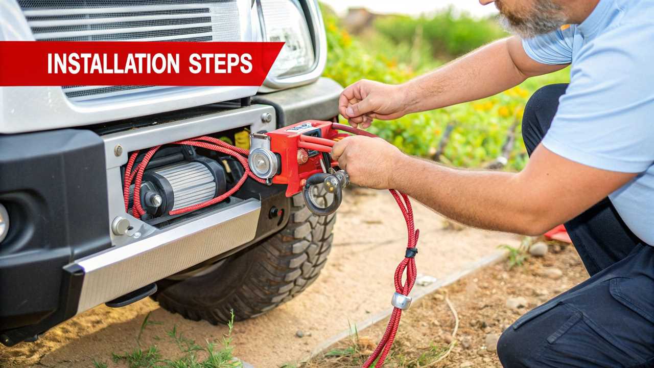
Wiring the Control Pack to the Winch Motor
Now it’s time to connect the control pack to the winch motor. You will use the short, color-coded cables that came with your winch.
Grab your Warn winch wiring diagram. The yellow, blue, and black cables must be attached to their matching posts on the winch motor, labeled F1, F2, and A. Don’t forget the small black ground wire for a solid connection.
This simple diagram breaks down how it all works together.
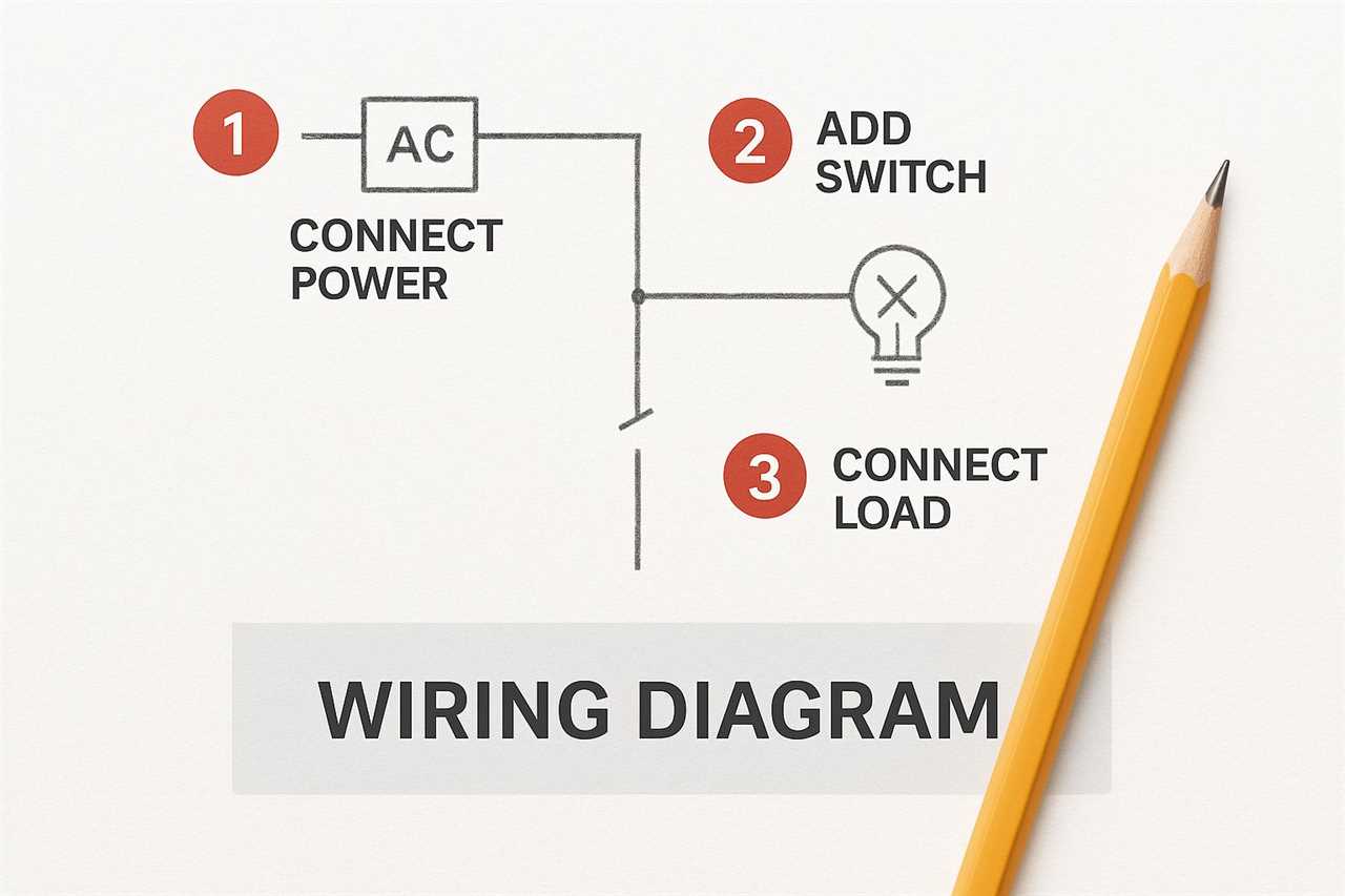
As you can see, those color-coded cables are the final link between the control pack’s commands and the motor’s muscle.
Protecting Your Connections
Damaged wiring is a common cause of winch failures. Pay close attention when routing these short motor cables. Keep them away from hot engine parts, sharp edges, and moving components.
A pro tip is to use protective wire loom or split tubing. It is cheap insurance for this short run from the control pack to the motor. This will prevent your cables from getting damaged.
Securing and shielding these wires now will prevent future frustration. For more walkthroughs, checking other expert guides on how to wire a winch can offer valuable perspective.
Connecting Main Power and Ground Cables
Now, let’s connect the heavy hitters. The long, thick red and black cables deliver serious power from your battery to the control pack. A winch can pull over 400 amps, so this direct connection is essential for safety.
Take your time routing these cables through the engine bay. Keep them clear of sharp edges, moving parts like belts, and hot exhaust components. Use plenty of zip ties or cable clamps to secure them tightly.
Securing a Solid Ground Connection
The black ground cable is just as critical as the positive one. A solid ground completes the circuit, and the best place for it is the battery’s negative terminal. This provides a direct and clean path.
A bad ground is the most common cause of winch problems. If your winch is slow or doesn’t work, check your ground first. Scrape off any paint or rust for a clean metal-to-metal contact.
Correct wiring is a critical safety measure. It ensures the winch operates as designed without causing electrical issues. For a technical deep dive, this guide on accurate cable sizing is a great resource.
Connecting the Remote and Testing Your Setup
With the main power cables connected, the final piece is the remote control. You still need to install the remote socket, whether you have a wired or wireless remote. This part of your Warn winch wiring diagram brings the system to life.
https://www.youtube.com/embed/S8GL8VCg7C8
Picking a mounting spot for the socket is a balancing act. You need easy access, but it should be protected from rocks or mud. Common spots include the front bumper or tucked away in the engine bay.
Final Power-Up and Test
Once every wire is connected, it’s time to bring it online. Reconnect the battery, positive cable first, then the negative. This is the moment of truth.
Before spooling the cable under load, you must do a no-load test. Freespool the clutch, pull out a few feet of rope by hand, then lock the clutch. This is a critical safety check.
Now grab your remote and slowly power the winch in and out. As you do, pay attention to a couple of things:
- Check Direction: Does “in” on the remote pull the cable in? If not, your F1 and F2 cables are likely swapped.
- Listen: The motor should run with a smooth, consistent hum. Stop immediately if you hear grinding, clicking, or binding noises.
A good result here means you’re ready for the trail. To learn more about what to do next, check out our full guide on how to use a winch correctly.
Common Questions About Warn Winch Wiring
Even with a perfect diagram, questions can arise during a winch installation. This is normal when dealing with high-amperage systems. We have compiled some of the most common issues people face.
People often ask if they can use a cheaper, aftermarket solenoid. I strongly advise against it. The Warn control pack is built to handle the massive power draw from its motors.
A classic issue is when the winch only spools in one direction. This is almost always because the F1 and F2 motor cables were mixed up. Disconnect the battery, swap those two cables, and you should be fine.
Troubleshooting and Best Practices
Your main power source is non-negotiable. A winch must be wired directly to your vehicle’s main battery. Tapping into another electrical system is a recipe for disaster.
The main black cable from the control pack must go straight to the battery’s negative terminal. If your model has a second, smaller ground wire, bolt it to a clean, unpainted spot on the frame. A weak ground is a notorious culprit for poor winch performance.
Finally, consider the winch line itself. Understanding the differences between materials is crucial. It’s worth exploring the debate on synthetic winch rope vs steel cable to ensure you have the best setup.
At Offroading.com, we’re dedicated to helping you tackle every project with confidence. From detailed wiring guides to gear reviews, find everything you need to hit the trail prepared at https://www.offroading.com.
https://offroading.com/warn-winch-wiring-diagram/?utm_source=rss&utm_medium=rss&utm_campaign=warn-winch-wiring-diagram
Did you miss our previous article...
https://manstuffnews.com/4x4-off-road-cars/a-guide-to-off-road-vehicle-recovery