A tail light wiring diagram is your roadmap to your vehicle’s rear lighting. It shows how your tail lights connect to power and to each other. It uses symbols and colored lines for brake lights, turn signals, and running lights.
Understanding this diagram is the first step for any successful repair or custom project.
Reading a Tail Light Diagram Like a Pro

Before touching any wires, you must learn to decode your vehicle’s electrical map. A tail light wiring diagram can look intimidating, but it’s your best tool to avoid costly mistakes. It transforms a messy bundle of wires into a logical system.
This isn’t just about matching colors; it’s about understanding your car’s electrical language. A good diagram helps you trace the main power wire, find paths to each light, and locate the ground. This knowledge eliminates guesswork that can blow fuses or damage electronics.
Understanding The Basics
At its core, a tail light diagram is about safety and function. The system has evolved to meet increasing demands for vehicle visibility. The first international rules for rear lighting appeared in the 1920s to make night driving safer.
You can learn more about the history of automotive lighting regulations to see how much things have changed.
Key Takeaway: Getting comfortable with the diagram is the one skill that separates a frustrating weekend project from a successful, safe repair. It’s what protects both you and your vehicle from easily avoidable electrical problems.
The schematic shows how different circuits work together. It clarifies how the brake light and turn signal circuits are separate, even if they share a bulb. This is a common point of confusion for many DIYers.
Here is a quick reference for common wire colors and their functions. Remember that your vehicle might have its own quirks, so always check your specific diagram.
Common Tail Light Wire Color Codes and Functions
| Wire Color |
Standard Function |
Circuit Description |
| Red |
Brake Lights |
Carries power to the brake lights when the brake pedal is pressed. |
| Green |
Right Turn Signal / Brake |
Powers the right-side turn signal and often shares the brake light function. |
| Yellow |
Left Turn Signal / Brake |
Powers the left-side turn signal and often shares the brake light function. |
| Brown |
Running/Parking Lights |
Provides constant power for tail lights and side markers when headlights are on. |
| White |
Ground |
Completes the circuit by connecting back to the vehicle’s chassis. The most critical wire! |
| Black |
Main Power Feed |
Sometimes used as the primary 12V+ power source for the entire lighting harness. |
This table is a good starting point. However, the golden rule is to always trust your vehicle-specific diagram over a generic guide. It’s the only way to be 100% sure you’re connecting everything correctly.
Your Essential Toolkit and Safety Checklist
Before you remove a tail light lens, let’s discuss what you need. A successful tail light project requires the right tools and a safety-first mindset.
You don’t need a professional garage, but a few key items are non-negotiable. Gathering them beforehand avoids mid-project trips to the store and ensures clean, reliable connections.
More important than any tool is your approach to safety. Working with your car’s electrical system has manageable risks. Follow these habits to protect yourself and your vehicle’s electronics.
Must-Have Tools for the Job
Let’s ensure you have the basics covered. Good tools make the work easier and ensure a durable, professional repair.
- Wire Strippers and Crimpers: Get a quality combination tool. It strips insulation cleanly without nicking the copper wires. You will also use it to create secure crimps on new terminals.
- Multimeter: This gadget is your best friend for electrical work. It confirms a circuit is dead before you touch it and helps identify wires if colors don’t match.
- Basic Hand Tools: You’ll need a socket set, screwdrivers, and pliers. These help remove the tail light assembly and access the wiring harness.
Non-Negotiable Safety Steps
Always, always, always disconnect the negative terminal on your vehicle’s battery before starting any electrical work. This simple action prevents short circuits that can damage expensive computer modules or even cause a fire.
After disconnecting the battery, use your multimeter for a final check. Set it to DC voltage and test the contacts in the wiring connector. Seeing “0V” confirms it’s safe to start work.
A Practical Guide to Wiring Your Tail Lights
Now, let’s turn that tail light wiring diagram into a real-world fix. It’s one thing to see it on paper and another to apply it to your vehicle. We’ll cover the process from accessing the assembly to making lasting connections.
Proper technique is crucial. When stripping a wire, be gentle to avoid nicking the copper strands. A quality crimper will create a solid mechanical bond that won’t vibrate loose.
This flow chart gives you a bird’s-eye view of a solid wiring job.
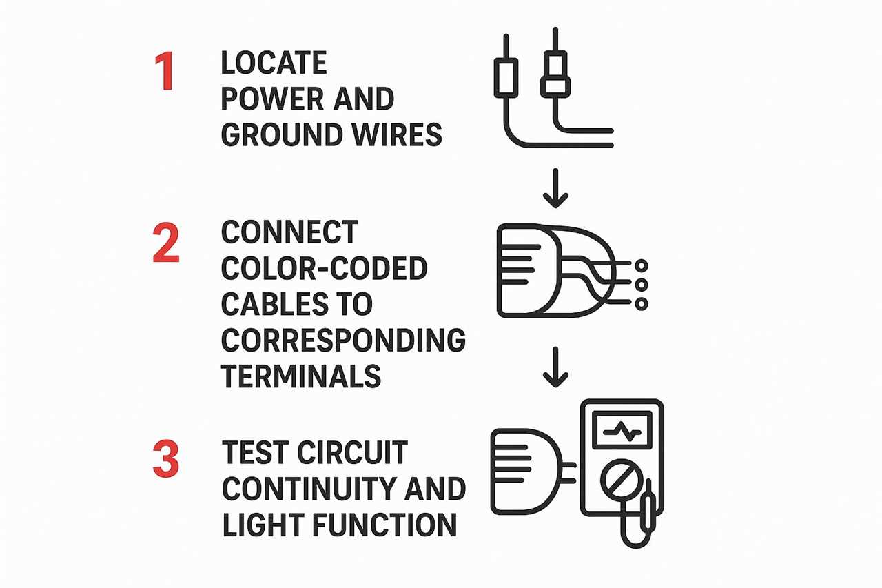
As you can see, the process is a logical sequence. You must confirm your power and ground are solid before connecting individual light functions.
Making Secure Connections
In custom builds, factory wiring standards may not apply. For example, a four-wire system might use a tan wire for tail lights and purple for brakes. Yellow and white could handle left and right signals.
These setups often use separate filaments or LEDs for different functions. Getting these connections right is critical for being seen on the road.
Crucial Tip: A clean, solid ground connection is absolutely non-negotiable. I can’t tell you how many lighting problems I’ve chased down that ended up being a bad ground. Make sure the contact point on the vehicle’s chassis is scraped down to bare, unpainted metal.
Once your new wiring is in place, route it smartly. Keep it away from hot exhaust pipes and moving suspension parts. These principles apply to all wiring jobs, including those in our guide on how to wire a winch.
Upgrading to LED Tail Lights Correctly

Swapping incandescent tail lights for LEDs is a popular upgrade. It improves looks and visibility but is rarely plug-and-play.
The main issue is that LEDs draw much less power than old bulbs. This can confuse your vehicle’s electrical system. The computer might think a bulb is burnt out, causing a dash warning or a fast-blinking turn signal.
This rapid blinking is called “hyperflash.” It’s your car’s warning that something is wrong with the turn signal circuit. Thankfully, there are solid fixes to make your new lights work properly.
Solving Common LED Upgrade Problems
To fix hyperflash, you need to add electrical resistance back into the circuit. This makes the system think the old bulb is still there. You can do this in one of two ways.
- Inline Resistors: These are wired in parallel, connecting to the turn signal’s power and ground wires. Be careful where you mount them, as they get hot. Secure them to a metal surface away from plastic or other wiring.
- Flasher Relays: On some vehicles, you can swap the stock flasher relay for an LED-compatible one. This is often a cleaner and easier solution than splicing in resistors.
Modern vehicle electronics have evolved since the 2000s. Many use smart control modules to manage lights and protect LEDs from voltage spikes.
Pro Tip: Before you start cutting wires to install resistors, do a quick search to see if an LED-compatible flasher relay exists for your vehicle. It could save you a ton of time and prevent headaches down the road.
If you’re unsure which lighting technology is best, it helps to understand all options. For a deep dive, see our guide comparing HID vs. LED vs. halogen lights for your vehicle.
Troubleshooting Common Wiring Issues
Even when you follow a tail light wiring diagram perfectly, things can go wrong. It’s frustrating when lights don’t work or only one function operates correctly. Logical troubleshooting can save you from pulling your hair out.
Before tearing apart your work, start with the most likely culprits. A quick look at the fuse box should always be your first move. This simple step can save a lot of time.
If the fuses are good, check the ground connection next. A bad ground causes many electrical problems, from dim lights to dead circuits. A little corrosion is all it takes to disrupt the system.
Finding The Fault
Your multimeter is the best tool for hunting down electrical problems. Start by testing for voltage at the tail light connector. This tells you if power is reaching the light assembly.
If you get zero voltage, the problem is further up the line. It could be a break in the wire or a bad connection.
A classic scenario is a short circuit. This happens when a power wire touches the vehicle’s metal frame. You’ll know it’s a short because it will almost always blow a fuse instantly. Finding the exact spot requires patiently tracing the wire’s path to see where it’s been pinched or damaged.
This quick troubleshooting table connects symptoms to likely causes and solutions.
Common Tail Light Issues and Solutions
| Symptom |
Potential Cause |
How to Fix |
| No lights work at all |
Blown fuse, bad master ground, or main power wire break. |
Check the fuse box first. Then, clean and tighten the main ground connection. Use a multimeter to test for power at the start of the circuit. |
| Lights are dim or flicker |
Poor ground connection at the light or a corroded bulb socket. |
Clean the ground point for the specific light until it’s shiny metal. Inspect the bulb socket and contacts for rust or corrosion and clean them. |
| One function fails (e.g., brake light) |
Burnt-out filament in a dual-filament bulb, or a break in that specific wire. |
Replace the bulb. If that doesn’t work, test for voltage on the specific wire (e.g., the brake light wire) at the connector when the pedal is pressed. |
| Brake lights and turn signals don’t work |
Faulty brake light switch or turn signal flasher relay. |
Test the brake light switch near the pedal for continuity. Check the flasher relay (you can often hear it clicking; if not, it may be bad). |
| Fuse blows immediately |
A short circuit where a power wire is touching the chassis ground. |
Disconnect the tail light harness. If the new fuse doesn’t blow, the short is in the light housing. If it still blows, meticulously inspect the wiring harness for damage. |
This table provides a solid starting point for diagnosis. Work methodically from the simplest fix to the most complex.
Maintaining your vehicle’s entire electrical system is key. Knowing how to stop and prevent radiator leaks can prevent coolant from damaging a nearby wiring harness, avoiding new electrical issues.
Answering Your Lingering Tail Light Wiring Questions
Even after a successful project, you might have some questions. Understanding the finer points of a tail light wiring diagram builds confidence for future tasks.
We’ve gathered common questions that arise during tail light jobs. This FAQ covers “what if” scenarios and helps you master the details.
Can I Use a Wiring Diagram from a Different Car Model?
I get this question a lot, and the answer is a hard no. It’s a very bad idea.
While all tail lights perform the same basic functions, their wiring is vehicle-specific. Wire colors, connector pin layouts, and circuit logic can vary between makes, models, and even model years.
Using the wrong diagram invites frustration and potential damage. You risk blowing fuses, having non-functional lights, or frying a Body Control Module (BCM). Always find a tail light wiring diagram for your vehicle’s exact year, make, and model.
What Is a Bad Ground and How Do I Fix It?
A “bad ground” is a top suspect for many electrical issues. It causes flickering, dim, or dead lights. This happens when the ground wire’s connection to the chassis becomes loose or corroded.
Electricity needs a complete loop to flow. A bad ground breaks this path.
Expert Tip: Fixing a bad ground is usually simple. Find the ground wire bolted to the chassis near the tail light. Unbolt it, then use a wire brush to clean the wire’s terminal and the frame’s contact point. You want to see shiny metal on both surfaces before bolting it back securely.
Do I Need to Add a Relay for My Tail Lights?
For standard bulbs or most LED replacements, you do not need a relay. The factory wiring is designed to handle the stock electrical load. The circuits are more than capable of the job.
However, a relay is essential if you add high-power lights. This includes auxiliary reverse pods or extra brake lights. A relay uses the original tail light wire as a low-power trigger to switch a new, heavy-duty circuit that pulls power directly from the battery. This protects your stock wiring from a load it was not designed for.
At Offroading.com, our goal is to give you the confidence to tackle any project, whether it’s simple wiring or a full-on vehicle build. Dive into our huge library of expert guides and tutorials and get ready to master your next off-road challenge.
https://offroading.com/tail-light-wiring-diagram/?utm_source=rss&utm_medium=rss&utm_campaign=tail-light-wiring-diagram
Did you miss our previous article...
https://manstuffnews.com/4x4-off-road-cars/changing-transmission-fluid-toyota-4runner-diy-guide